Using an ATTINY85 microcontroller to water a plant
I tend to forget watering my plants sometimes, so mainly buy succulents that don't mind drying out in between watering, but sometimes I would like having some plants like fresh herbs.
To solve this issue I was planning to use an Arduino to automate this task. With some basic electronics or a relay module I would like to turn on a small pump when the soil is dry. All parts can be bought on Aliexpress quite cheap. Here are some parts that I have ordered:
This was a good setup, but I noticed the moisture sensor was reacting very slow when I added water to the soil. Because of this my program did not work very well when I just used the sensor to indicate when the plant received enough water, as a fail safe I also limit the time to 10 seconds when watering the plant and then there needs to pass at least 24 hours before watering the plant again.
This solved that issue, but it was something that kept annoying me and I had one sensor that I had bought from an other seller that did not have that issue. After googling that issue I found a video that explained what caused it and how to resolve it, so I will not go in detail about it here.
Flaura's explanation and solution
After connecting all the parts and testing some basic code that I found online and changed to my liking it worked well and I started thinking of how to make it more practical. The Arduino nano is overpowered and relay module is also quite large, making it difficult to make it look nice and discrete.
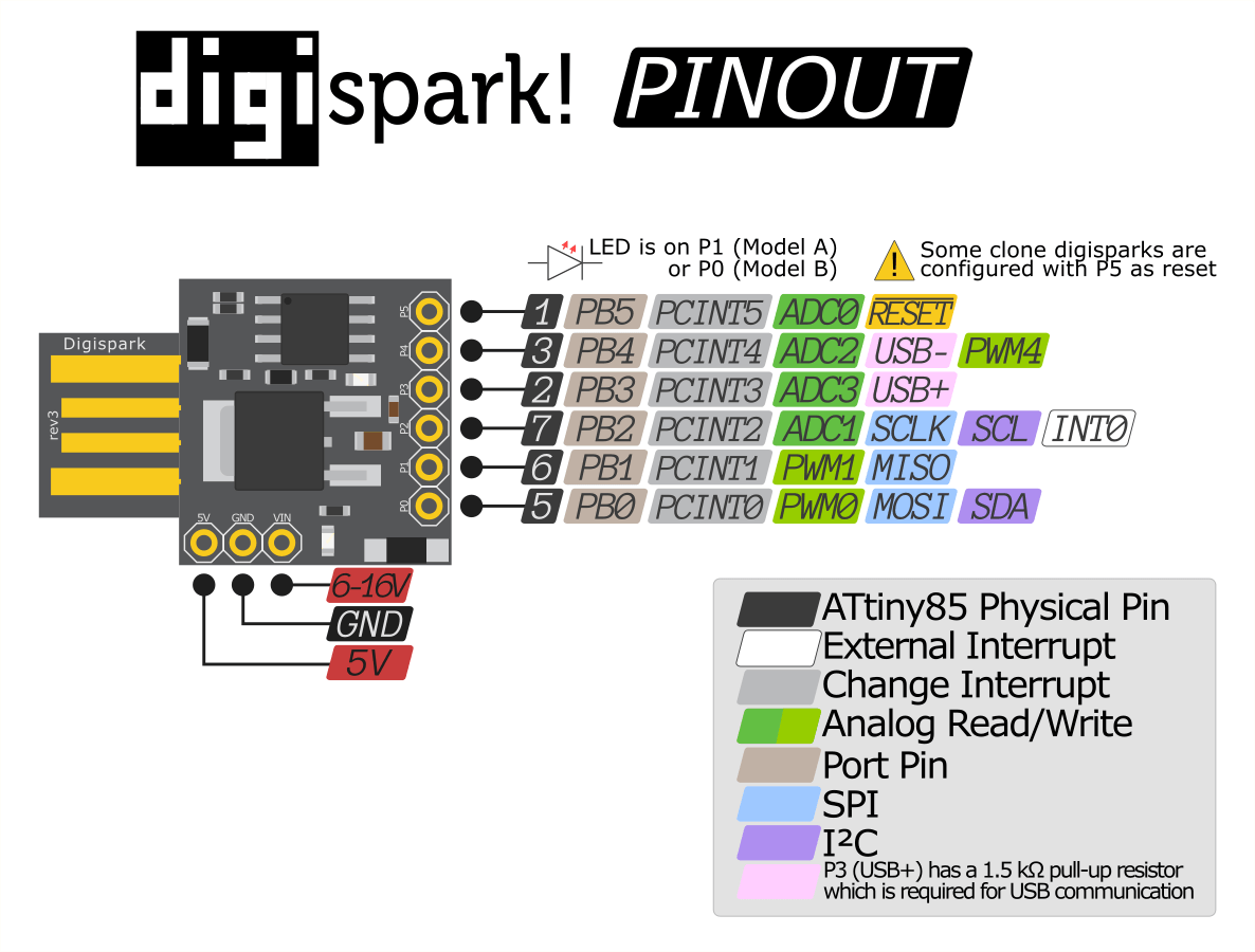
When shopping on Aliexpress for parts I also found some other micro-controller boards that were a lot more compact. I like the ones based on the ATTINY85, a small 8 pin Atmel micro-processor. There are small development boards available from Digispark and it it is also possible to only buy the controller in a dip-8 package in case I would like to make a custom PCB for it.
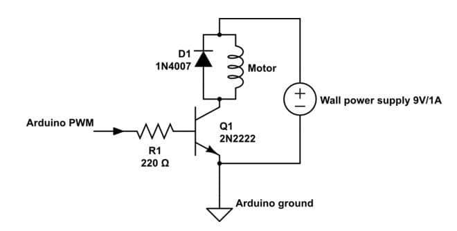
The relay module was going to be replaced by a 2N2222a transistor, resister and 1N4007 diode. Since the little pump work on the same 5 volts as the Arduino I do not need to use an external power supply, but apart from that it is the same as the schematic below:
To make it as compact as possible I will solder the controller board directly on the back of the soil sensor's 5V and ground pins. The transistor and other components will be wired together using their pins in front of the sensor and is connected to pin 1 of the controller board. A wire connects the voltage out of the sensor to ping 5 of the controller. Some heat shrink will cover both output pins when I connect the pump to them.
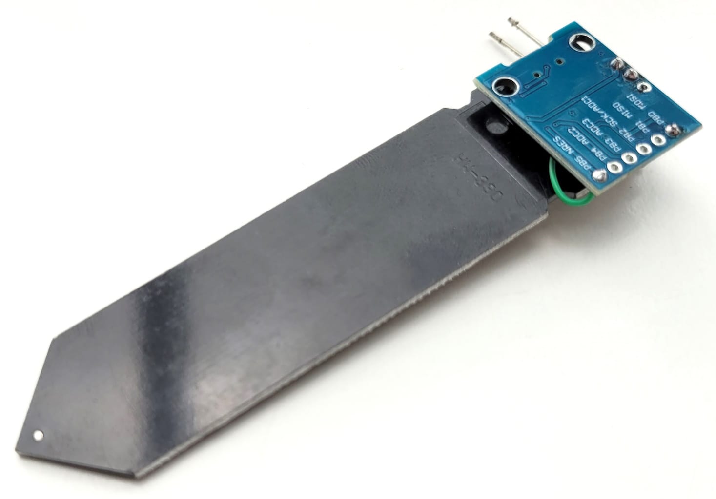
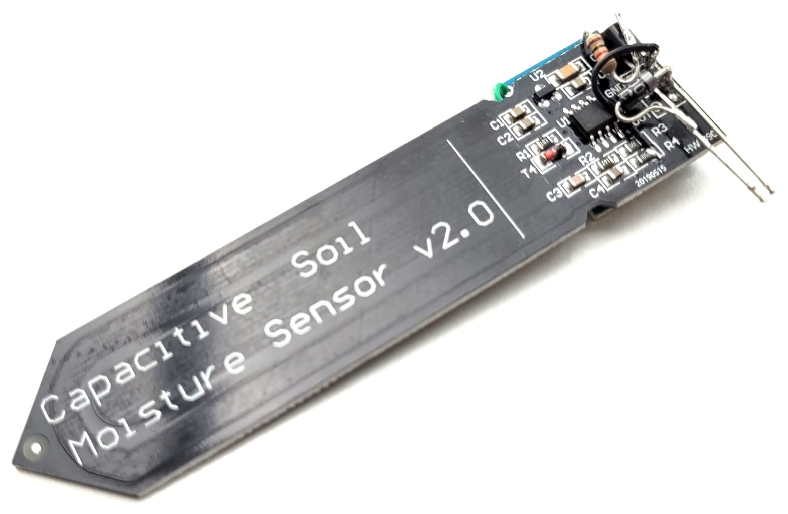
Everything connected together
Now it is time to program the controller using the Arduino IDE. To be able to use these ATTINY85 board with Arduino you need to add the Digispark board to the boards manager by adding the link digistump_index.json link to the additional boards manager URL in the Arduino preferences. But at the time of writing that link was not working anymore, maybe Digistump abandoned that project?
I asked ChatGPT what repository he could recommend as an alternative and the first suggestion was ArminJo's DigistumpArduino Repository and it worked perfectly for me. Next I asked if he could show me the corresponding analog pins that I should use in the arduino IDE and that gave the next table:
| Arduino Pin | Analog Pin | Physical Pin | Notes |
|---|---|---|---|
| 0 | A0 | 7 | P0 on board |
| 1 | A1 | 6 | P1 on board |
| 2 | A2 | 3 | P4 on board |
| 3 | A3 | 2 | P3 on board |
| 4 | A4 | 1 | P2 on board |
As you can see they do not line up as you would expect, so it was a good thing to check. The Digital outputs lined up as expected, I have used P0 for the pump (0 in the IDE) and on P1 of the board is a build in LED (1 in the IDE).
After uploading the code there some issues, it did not seem to read the analog value from the sensor, so I checked the code further on an other digispark board to see what the issue was.
When connecting the soil sensor to pin 5 I noticed that the controller appeared to be restarting and I would never read any analog value on that pin. When searching online for this issue I read that some Digispark board clones would indeed configure this as a reset pin. It is something that can be changed by re-flashing the micronucleus kernel, but at the moment I would not bother with that, I have other pins I can try. I will connect the sensor to P2 (4 in the IDE).
That brings me to another annoying issue with small controllers: some of the pins will be used to program the controller when connecting it to the pc and they switch to their normal operation after starting up, but if you have something connected to those pins when you try to program the controller it will not work. So make sure your program is working before soldering components to those pins.
Not sure what caused it, maybe I shorted something when testing different configurations or maybe having the sensor connected to the same pin as the usb connection, but I was able to generate some magic smoke and probably damaged the micro controller. It is still working but I have ordered some more and will wait until they arrive to continue
To make it easier to debug the code and make sure everything is working correctly I will also connect my usb to serial board to one of the free pins and add code to monitor the values being read. Instructables has a good example of how to do this.
In my next update I will post the code and final design of the compact soil moisture sensor.